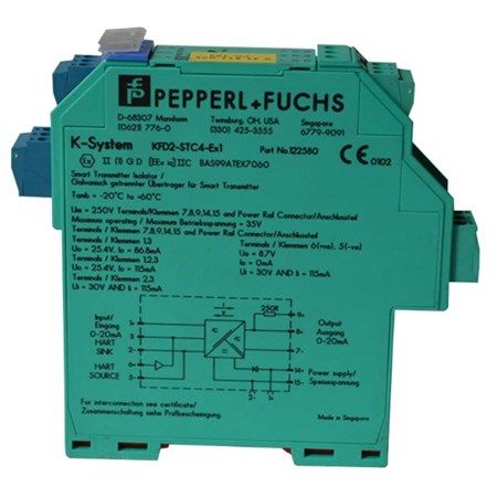
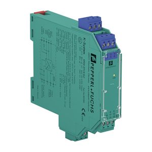
Pepperl+Fuchs KFD2-STC4-Ex1 SMART Transmitter Power Supply
ModelKFD2-STC4-EX1
SMART transmitter power supply, 1-channel isolated barrier. Input: 2-/3-wire SMART transmitters, 0/4–20 mA; output: 0/4–20 mA, load 0–800 Ω at 20 mA.
- Function
- SMART transmitter power supply, 1-channel isolated barrier
- Input
- 2-/3-wire SMART transmitters, 0/4–20 mA
- Output
- 0/4–20 mA, load 0–800 Ω at 20 mA
- Supply
- 20–35 V DC via Power Rail or terminals 14+, 15-
Availability and lead time confirmed on request
Overview
Pepperl+Fuchs KFD2-STC4-Ex1 SMART Transmitter Power Supply, 1-Channel Isolated Barrier
• 1-channel isolated barrier
• 24 V DC supply (Power Rail)
• Input 2-wire and 3-wire SMART transmitters and 2-wire SMART current sources
• Output 0/4 mA … 20 mA
• Terminals with test points
• Up to SIL 2 acc. to IEC 61508
Function of Pepperl+Fuchs KFD2-STC4-Ex1 SMART Transmitter Power Supply, 1-Channel Isolated Barrier
• This isolated barrier is used for intrinsic safety applications.
• The device supplies 2-wire and 3-wire SMART transmitters in a hazardous area, and can also be used with 2-wire SMART current sources.
• It transfers the analog input signal to the safe area as an isolated current value.
• Digital signals may be superimposed on the input signal in the hazardous or safe area and are transferred bi-directionally.
• If the HART communication resistance in the loop is too low,the internal resistance of 250 Ω between terminals 8 and 9 can be used.
• Test sockets for the connection of HART communicators are integrated into the terminals of the device.
Application of Pepperl+Fuchs KFD2-STC4-Ex1 SMART Transmitter Power Supply, 1-Channel Isolated Barrier
The device supports the following SMART protocols:
• HART
• BRAIN
• Foxboro
| General specifications of Pepperl+Fuchs KFD2-STC4-Ex1 SMART Transmitter Power Supply, 1-Channel Isolated Barrier |
|
| Signal type | Analog input |
| Functional safety related parameters | |
| Safety Integrity Level (SIL) | SIL 2 |
| Supply | |
| Connection | Power Rail or terminals 14+, 15- |
| Rated voltage | 20 … 35 V DC |
| Ripple | within the supply tolerance |
| Power dissipation | 1.4 W |
| Power consumption | 1.8 W |
| Input | |
| Connection side | field side |
| Connection | terminals 1+, 2-, 3 or 5-, 6+ |
| Input signal | 0/4 … 20 mA |
| Voltage drop | ≤ 2.4 V at 20 mA (terminals 5, 6) |
| Input resistance | ≤ 64 Ω terminals 2-, 3 ; ≤ 500 Ω terminals 1+, 3 (250 Ω load) |
| Available voltage | ≥ 16 V at 20 mA terminals 1+, 3 |
| Output | |
| Connection side | control side |
| Connection | terminals 7-, 8+, 9 |
| Load | 0 … 800 Ω at 20 mA |
| Output signal | 0/4 … 20 mA (overload > 25 mA) |
| Ripple | max. 50 µA rms |
| Transfer characteristics | |
| Deviation | at 20 °C (68 °F), 0/4 … 20 mA ≤ 10 µA incl. calibration, linearity, hysteresis, loads and fluctuations of supply voltage |
| Frequency range | field side into the control side: bandwidth with 0.5 Vpp signal 0 … 7.5 kHz (-3 dB) control side into the field side: bandwidth with 0.5 Vpp signal 0.3 … 7.5 kHz (-3 dB) |
| Settling time | 200 µs |
| Rise time/fall time | 20 µs |
| Indicators/settings | |
| Display elements | LED |
| Labeling | space for labeling at the front |
| Directive conformity | |
| Electromagnetic compatibility | |
| Directive 2014/30/EU | EN 61326-1:2013 (industrial locations) |
| Conformity | |
| Electromagnetic compatibility | NE 21:2011 |
| Degree of protection | IEC 60529:2001 |
| Ambient conditions | |
| Ambient temperature | -20 … 60 °C (-4 … 140 °F) |
| Mechanical specifications | |
| Degree of protection | IP20 |
| Connection | screw terminals |
| Mass | approx. 200 g |
| Dimensions | 20 x 124 x 115 mm (0.8 x 4.9 x 4.5 inch) , housing type B2 |
| Mounting | on 35 mm DIN mounting rail acc. to EN 60715:2001 |
| Data for application in connection with hazardous areas | |
| EU-Type Examination Certificate | BAS 99 ATEX 7060 X |
| Marking | II (1)G [Ex ia Ga] IIC , II (1)D [Ex ia Da] IIIC , I (M1) [Ex ia Ma] I |
| Certificate | TÜV 99 ATEX 1499 X |
| Marking | II 3G Ex nA II T4 [device in zone 2] |
| Directive conformity | |
| Directive 2014/34/EU | EN 60079-0:2012+A11:2013 , EN 60079-11:2012 , EN 60079-15:2010 |
| International approvals | |
| UL approval | |
| Control drawing | 116-0428 (cULus) |
| IECEx approval | IECEx BAS 04.0016X IECEx CML 15.0055X |
| Approved for | [Ex ia Ga] IIC, [Ex ia Da] IIIC, [Ex ia Ma] I Ex nA IIC T4 Gc |
Specifications
| Function | SMART transmitter power supply, 1-channel isolated barrier |
|---|---|
| Input | 2-/3-wire SMART transmitters, 0/4–20 mA |
| Output | 0/4–20 mA, load 0–800 Ω at 20 mA |
| Supply | 20–35 V DC via Power Rail or terminals 14+, 15- |
| Power consumption | 1.8 W |
| Functional safety | Up to SIL 2 (IEC/EN 61508) |
| Ambient temperature | -20 to 60 °C |
| Housing | 20 × 124 × 115 mm (W × H × D), 35 mm DIN rail |
| Ex certificate | BAS 99 ATEX 7060 X |
Source: Pepperl+Fuchs product page and data sheet KFD2-STC4-Ex1 (pds 283672). Confirm with the manufacturer datasheet before ordering.
Documents
- DatasheetPDF · on request Request
- Operating manualPDF · on request Request
- Certificate copy (with order, where available)PDF · on request Request
Downloads will be added after the files have been checked.
Same series
Other models in the same family as Pepperl+Fuchs KFD2-STC4-EX1.
Accessories and spares
Parts, licences and services made for Pepperl+Fuchs KFD2-STC4-EX1.

Frequently paired with
Often quoted together with Pepperl+Fuchs KFD2-STC4-EX1.